Basic definitions used in terms of cement and concrete
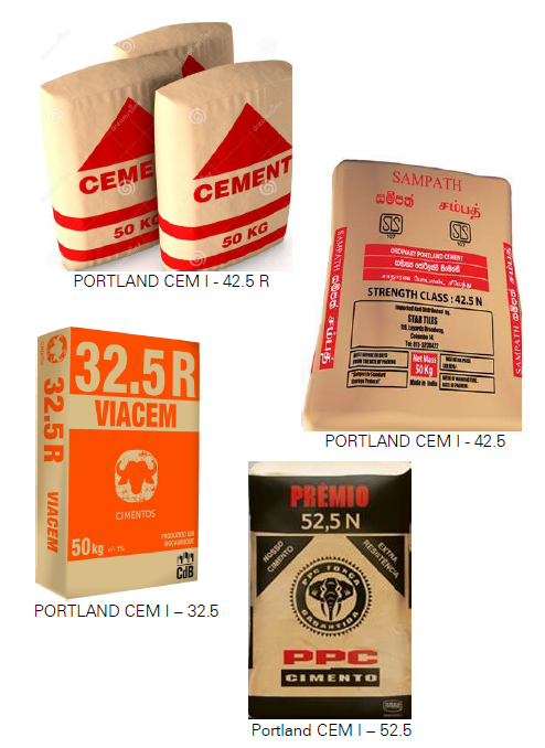
PORTLAND™ Cement: Material made by heating a mixture of limestone and clay in a kiln at about 1450°C, then grinding to a fine powder with a small addition of gypsum. Portland cement, the main subject of this project, is the most common type of cement – that is why we call it as 'basic cement'. In particular, ordinary Portland cement is the normal, grey, cement which the most of industry are familiar with. Other types of Portland cement include White Portland Cement and Sulphate Resisting Portland Cement (SRPC).
Clinker:
Portland cement is made by grinding clinker and a small amount of added gypsum. Clinker is a nodular material before it is ground up.
The nodules can be anything from 1mm to 30 mm or more in diameter.
Basic chemical information
Basic components of each Portland Cement (OPC):
Ca from CaCO3
Si from SiO2
AL from Al2O3
Fe from Fe2O3
Portland Cement (CEM I/II) is a composit of:
50% C3S Tricalciumsilicat chem. as 3CaOSiO2 Alit
25% C2S Dicalciumsilicat chem. as 2CaOSiO2 Belit
10% C3A Tricalciumaluminat chem. as 3CaOAl2O3
10% C2AF Calciumaluminatferrit chem. as 2CaOAl2O3Fe2O3
5% Gypsum chem. as CaSO4
Alite: Ca3 SiO5 in terms of its oxides is 3CaO SiO2. The CaO term is shortened to C and the SiO2 to S. The compound thus becomes C3S.
Belite: Similarly, Ca2 SiO4 is 2CaO SiO2, which is shortened to C2S.
Tricalcium Aluminate: Ca3 Al2 O6 is 3CaO Al2O3 . The Al2O3 term is shortened to A and the compound becomes C3A.
Tetracalcium Aluminoferrite: 2(Ca2 Al FeO5) is 4CaO Al2O3Fe2O3. Fe2O3 is shortened to F and the compound becomes C4AF.
Lime Saturation Factor
The LSF is a ratio of CaO to the other three main oxides. Applied to clinker, it is calculated as:
LSF=CaO / (2.8SiO2 + 1.2Al2O3 + 0.65Fe2O3)
Often this is referred to as a percentage and therefore multiplied by 100.
The LSF controls the ratio of Alite to Belite in the clinker. A clinker with a higher LSF will have a higher proportion of Alite to Belite than will be a clinker with a low LSF.
Typical LSF values in modern clinkers are 0.92-0.98, or 92%-98%.
Values above 1.0 indicate that free lime is likely to be present in the clinker. This is because, in principle, at LSF=1.0 all the free lime should have combined with Belite to form Alite. If the LSF is higher than 1.0, the surplus free lime has nothing with which to combine and will remain as free lime.
In practice, the mixing of raw materials is never perfect and there are always regions within the clinker where the LSF is locally a little above, or a little below, the target for the clinker as a whole. This means that there is almost always some residual free lime, even where the LSF is considerably below 1.0. It also means that to convert virtually all the Belite to Alite, an LSF slightly above 1.0 is needed.
The LSF calculation can also be applied to Portland cement containing clinker and gypsum if (0.7 x SO3) is subtracted from the CaO content. This calculation (0.7 x SO3) does not account for Sulphate present as clinker sulphate in the form of potassium and sodium sulphates and this will introduce a slight error. More particularly, it does not account for fine limestone or other material such as slag or fly ash in the cement. If these materials are present, calculation of the original clinker LSF becomes
more complex. Limestone can be quantified by measuring the CO2
content and the formula adjusted accordingly, but
if slag or fly ash are present, calculation of the original clinker LSF may not be conveniently practicable. To adjust the LSF formula under such more difficult circumstances needs to be involved professional chemists to train the process running staff engineers in a special course.
Silica Ratio (SR):
The silica ratio (also known as the Silica Modulus) is defined as:
SR = SiO2 / (Al2O3 + Fe2O3). A high silica ratio means that more calcium silicates are present in the clinker and less Aluminate and Ferrite. SR is typically between 2.0 and 3.0. The silica ratio is sometimes called the ‘silica modulus.’
Alumina Ratio (AR)
The alumina ratio is defined as: AR = (Al2O3 / (Fe2O3). This determines the potential relative proportions of Aluminate and Ferrite phase in the clinker. An increase in clinker AR (also sometimes written as A/F) means there will be proportionally more Aluminate and less Ferrite in the clinker. In ordinary Portland cement clinker, the AR is usually between 1 and 4.
The above three parameters are those most commonly used. A fourth, the 'Lime Combination Factor' (LCF) is the same as the LSF parameter, but with the clinker free lime content subtracted from the total CaO content. With an LCF=1.0, therefore, the maximum amount of silica is present as C3S.
Where coal is the fuel for the kiln, the raw mix composition has also to take into account the effect of coal ash, as much of the ash will become incorporated into the clinker. The quantity of ash is enough to have a significant effect on clinker composition - ash may represent perhaps 2%-3%, or more, of the clinker. So, this effect can have a significant influence on the chemistry of the ALHEDAB Cement project.
Strength classes (grades) according EN 197-1 standard
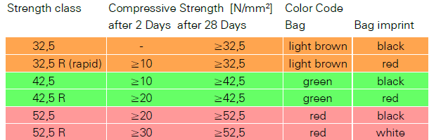
We differ between different strength classes in order avoid mixing-up their resistance against stress in the later concrete. On the other hand we use this distinctive future to hallmark simultaneously the hardening interval time of those grades. That means we use a significant strength grad development up to two days with partial grad development or up to 28 days to reach their full strength grade. To avoid misusing are the bags imprinted by a colour code as shown above. It may sometimes be changed by cement manufacturers in several countries, but being according standard EN 197-1 those colours are obliging. So, to ALHEDAB Cement is strongly recommended using this colour code as well. Except of the chemical and mineralogical composition of cements is its finesses important for their technical features. Basically can be said, more fine cement develops a higher strength. The specific surface of cement particle, also called as BLAINE, will be used as the grade of fineness and is between 2,500 and 5,000 cm2/g. In the valid Europe standard for slow (L) and fast (R) hardened cements will be differed between the strength grades 32.5 / 42.5 / 52.5 MPa or N/mm² either. Gaining the best cement prices on the market means for ALHEDAB Cement to manufacture according the given grades, packed in the right bags and certifying the entire production without any irritations according the standard.
Cement Chemical Technology
At this point shall be mentioned at first, that this study does not refers to the wet cement process and wet technology. This older technology has been gone for decades and will not come back because of the very high fuel and energy consumption. So, in the antagonism to other feasibility study consultancies, IRD Swiss Research would never show any interests in wasting time and paperwork to discuss endless the advantages or disadvantages of the wet technology to manufacture cement nowadays. That means we only provide in the following cement technology considerations the dry process that is in the cement world of today a very well-known process, developed to its high-end status.
Cement manufacturing starts with quarrying the raw materials as we have discussed in the prior cement chemistry chapter. First of all, it will be needed the Limestone that occurs in the ALHEDAB reserved area of Nalut as a very rich in substance Limestone as a low mountainous belt of rock. Its chemistry shows a bright character of lime geodes inside, lays, fresh broken, bright and of light grey, very uniformly in this rock belt.
To look at one typically chemistry content line of this limestone we have chosen sample No. 4 drilled from the depth of 10-20m from a whole at the coordinates of N 31° 43’ 19.96” / E 10° 52’ 6.34” (APPENDIX X-1) shown as follows:

This sample was taken in 1975 during the big National geological survey, the National geographic and mining institute of Libya had ordered. The local sampling around Nalut area is quite rough, so right after project start, we have to raster a more compacted and closer drilling scheme in order to get better and more precisely analysis results from the planned quarry field of limestone around Mazuzah member formation.
The same we have to execute for the planned Gypsum quarry field N 32° 3’ 57.78” / E 10° 57’ 54.78” right of Umm al-Far direct in North of Nalut, only about 60 KM far from plant site. For that we gave order to analyse some found sample from ground bottom of the field. This would be a big advantage in the opposite to obtain the needed Gypsum from the largest Libyan Gypsum quarry, that is more than 250KM far from plant site.
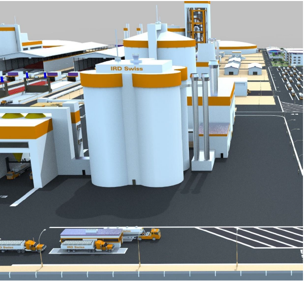
Especially the CaO assay, more than 54% is one very good aspect to speak about a very suitable Limestone but there are also some small variations in assay of other chemical compounds, so it has to be clear that the transported Limestone into the plant stock has to be stored into a circular stock bin, where the raw material must be layered-up while moving-in on a circle to avoid chemical misplacements and differences in basic of the assays of the Limestone as much as possible (pre-blending storing). Longitudinal bins, as at older cement plants would be not good enough. That is why we decide installing one
circular stock tent with a diameter of 100m for each cement line separately.
Quarry Technology The ALHEDAB Limestone claim is a belt of stone rock with an open front end, edged in a wide of about 5 KM skewing to the road, shown here:
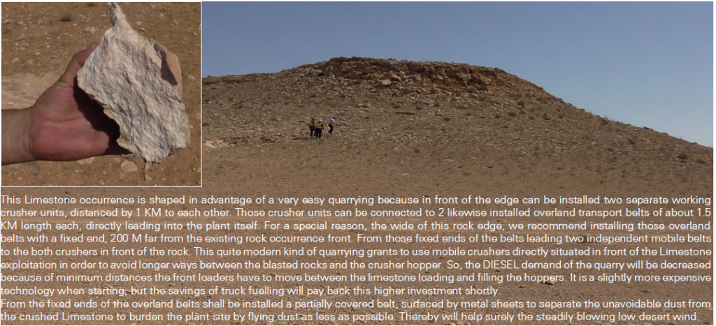
The clay, moved from 65KM disconnected Northern clay quarry at Wazen City, comes by truck into the plant in the same way as the Gypsum from the 60KM disconnected Gypsum quarry Umm Al-Far will be delivered, even on the same road.
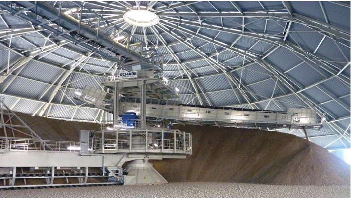
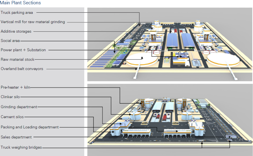
As shown left, the overland transport belt brings the crushed Limestone from the quarry directly into a circular stock bin where the raw material will be layered-up in a circle bin, so called pre-blending storage. Pre-blending means the raw Limestone, collected from different places in the quarry, equipped with low chemical assay differences, will be mixed to a more homogeneous material, avoiding larger assay gaps in chemistry of Limestone. This fact is very important because otherwise the material matrix composition will be more difficult to handle in proportioning part to be controlled in the cement burning process where the Alite and Belite phases, mentioned as very important in the cement chemistry part of this study before, can be developed in the right time and amount. If we remember the time in the past where the most of manufacturers only had longitudinal bins for storing the crushed
Limestone, they faced strong problems in that. So, there is no way beside this technology as it is kind of the art of today’s storing the raw materials coming in from the quarry. This technology consist of a belt, coming from the top of the storage tent roof, bringing the material from quarry, down on a stacker what is circulating in a circle of 270 degree, a scraper below that, cutting horizontally the bin and stacks the raw material on an outgoing next belt that leads direct into the raw milling department, the next station within the plant site so far, considered next.
Additive Storage Technology
To provide the cement process with the needed amounts of additives has to be installed an additive storage facility. According the requirements of plant shall be delivered the Clay from the clay quarry onto the clay yard inside the plant by truck as distinguished from Limestone conveying way into the plant site the Clay and the Gypsum have to enter via a supplier gate directly onto clay and Gypsum yard. This is a special wish of the ALHEDAB management in order to avoid supplying the clay simultaneously with in- and outgoing cement trucks. It makes sense, especially because
the plant needs about 24% clay of about 3,120 TPD (tons per day). To carry this amount of clay needs about 80 trucks per day driving 65KM to and 65KM from the quarry into the plant. Multiplied with 330 operating days/year, the plant has to face more cost. That is why IRD Swiss recommends aspirating a third-party delivery contract for both, Clay and Gypsum. The same is valid for the less amount of Iron ore and the Sand, the cement process needs.
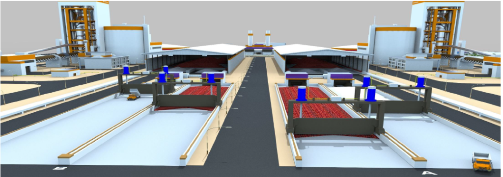
The picture shown below indicates a useful facility how to operate two independent workable additive yards and storages for a double line plant as ALHEDAB wants to establish. In the red yards will be kept the clay, in the white ones Gypsum is being
kept. Materials in all yards will be moved directly in a separate roller crusher by hydraulic sliding windlasses, no personnel staff needed. Crushed materials are being kept in roofed yards
Raw Material Proportioning
Before milling the raw materials and the process additives to be needed, all of those have to be proportioned in the right sufficient lots by weighing out their masses.
At this will be given by two separate belts according the LSF (Cement formula) the needed Limestone amount,
the Clay amount, the Sand amount and maybe some Iron Ore, on a weigh feeder,
where electronically will be balanced out all parts, controlled by the master control
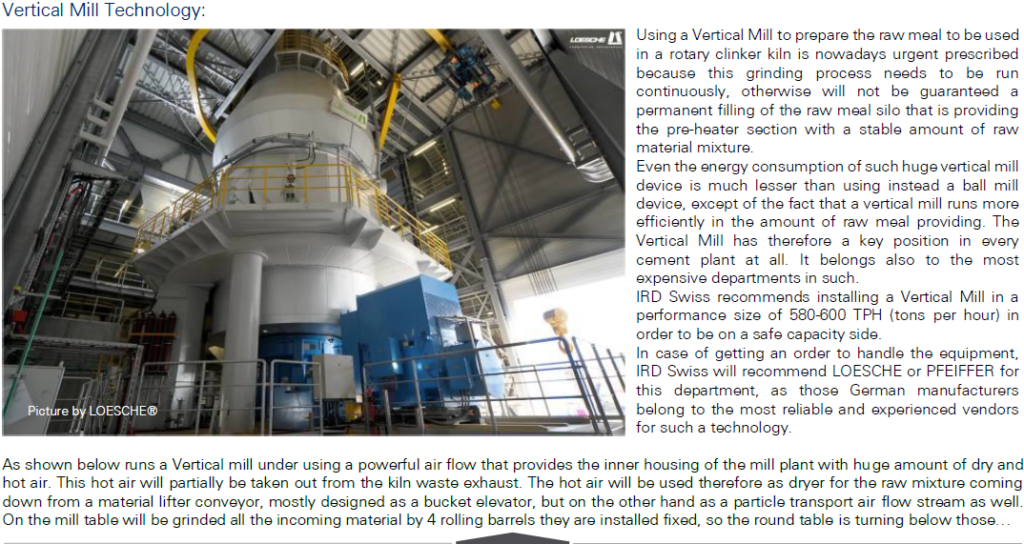
software, to be needed for the kiln process. Then, correct weighted, will be fed an elevator that lifts-up the raw material mix into the top of the Vertical Mill to be grinded there in the necessary particle sizes. IRD Swiss recommends choosing only the best equipment for this weighing hardware to avoid unnecessary breaks in continuing the pre-mill process and to be safe in supply the kiln process with the exactly weighted raw meal mix, as this device is very important for the following manufacturing process of the cement clinker.
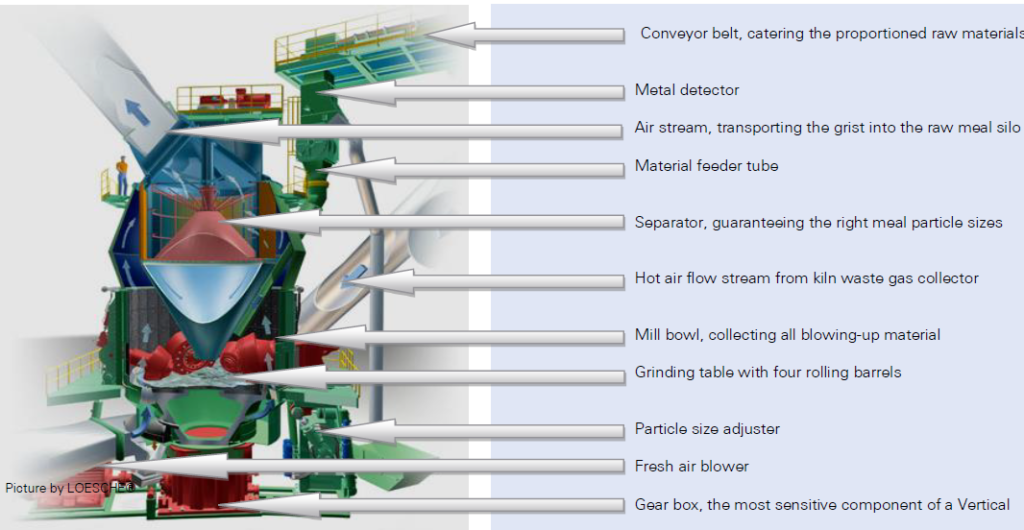
Raw Material Homogenization after grinding
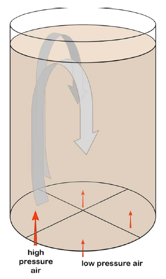
The raw meal, grinded by the Vertical Mill will be moved, called so as grist, directly into a homogenization silo on the top of it. Inside gets the grist a circulation through the height of the silo (about 30 M for each 6000 TPD line) by air streams of two different forces to gain a maximum intermix of the material matrix entirely. The homogenization silo contains a 3-day supply of the raw meal. On the bottom of the silo is a scraper located to pull out the homogenized raw material to feed it to a bucket elevator alongside the next department of the plant, the pre-heater tower.
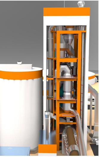
The pre-heater tower itself is the highest construction in the plant and has to correlate to the requirements, given by the licence to plant to a maximum height of 100 M. That is why IRD Swiss recommends by this study to hold this max height to avoid sanctions in that regard. The tower shall be designed and equipped with 5 stages (5 funnels) to warrant an effective warm-up of the raw meal as much as possible by running down through the shells against the waste gas hot air stream from the kiln tertiary air duct tube and the pre-calciner. An optimum warming-up process would be reached when the highest and 1st funnel (on the top) has an inside temperature of nearly 300°C and the 5th funnel, before the pre-calciner entrance is reached, a temperature of 450°C. When entering the pre-calciner the material will be heated-up for the first time by an active heater, the calciner burner. This burner shall heat the raw mix up to 650°C as it is for an optimum pre-heating circuit required. After passing the pre-calcination process where the Ca atoms will be slightly cracked already from Oxygen connecting, the material enters the rotary kiln in order to be running through the burning phases. The efficiency of such modern pre-calciners have reached especially within the last 5 years a high standard and can also be used when fired by secondary fuels like wastes, tyres or other combustible sources and materials that are available.
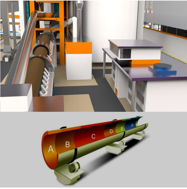
The kiln is the heart of each cement plant and as do so, it has to be designed and installed as exactly as needful to the required technology of the client and his conditions. Those conditions are on the first hand the raw materials but also the fuel with what the kiln shall be fired. On the other hand, is the kiln process mainly responsible for the success or failing of the plant efficiency. The scientific and technical literature is full of theoretical calculations, design requirements, sizes and other hints, suitable more or less. IRD Swiss designs their ovens according long-term experiences and current aspects new, for each customer tailor made. That means after evaluation of each material analysis, given by own feasibility studies, full computer-aided technology development and finalized burning and combustion scheme, will the design be made by our specialists without any compromises in hard ware, prices and ordered only at the best suppliers. We slope our kiln tubes downwards in head direction up to 4 degree and lay it out to 3-4 rpm turning speed, only driven by SIEMENS® high frequency motors and FLENDER® gearboxes. See the zones from left below:
A – Clinker outlet, where the hot clinker falls on cooler
B – Transition zone, the material became to Clinker
C – Flame zone, heating-up material to 1450°C
D – Upper transition zone, where burning phase starts
E – Security region, collected all material at no stress
F – Calcination zone, completes the calcining phase
G – Inlet zone, entrance of the material from pre-calciner
GAS Plant Technology In order to supply the kiln with fuel we have in Libya two technical possibilities that are given by the licence for ALHEDAB plant, to fire the kilns by Gas fuel or HFO oil. Combustion of delivered Gas by blowing-in directly into the kiln together with air pressure. To be ignited, creates Gas a very sufficient and clean flame, so combustion process can be used as the cleanest cement burning process that can be installed. If HFO or crude oil shall be used as second (dual) fuel, the delivered oil has to be moved from a tank up to the head of kiln and has to be blown-in
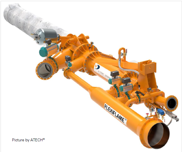
under usage of compressed air of 40 bar pressure where the oil will be loaded up to a spray. This oil spray can be ignited in the same way the Gas can be. The given example by a very reliable dual fuel burning system is been showed left hand side. The FLEXIFLAME® dual burner includes two different connections for two separate fuels. In that case HFO plus NGAS. Because of the special requirements ALHEDAB wants to be realised both kilns from line A and line B can be fired by GAS and/or Crude Oil. That gives the plant a most flexible using of two different fuels that are normally permanent available, but being afraid of some incidental or possible shortages can be switched easily during manufacturing process with on or both lines. Because of some special process routines must be followed some required safe guidelines to do so. That is why a special task force team has to be trained by the manufacturer of this dual burning system. There are in principle two market leader in that technique on the market, PILLARD France and ATECH Germany. It is not decided yet, which company will be charged for. While the gas tubes will be installed directly from the Gas dividing station to the head of the kilns, the Crude oil pipes will just be led into a special Oil department in order to prepare the heavy running Oil on physical and chemical way and to provide a better fluidity of the Crude Oil. That is very important to create sufficient Oil spray that is good enough to be ignited trouble-free
Clinker Cooler Technology Cooling down the Clinker in a very short time is the challenge of a cement engineering company, because the hot clinker, falling down from the kiln head has still about 1400°C when leaving the kiln. To be able to store the clinker in a Clinker silo we just can enter such of a normal temperature of the clinker by 60-65°C. The range between both, hot and normal clinker temperature has to be detracted from it. A lot of cooler designs are well known therefore, but IRD Swiss prefers the new age cooler design of IKN® Germany because of its efficiency under using low cooler size
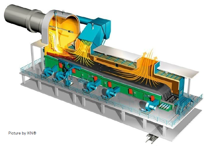
Only a cooler surface size of 25x5.5 M is necessary to cool down the temperature range of 1350°C. By designing of special cooler blades, called as COANDA Wings, streams cold air through those and propels the hot material temperature from two separate zones, a tertiary duct zone and a cooler case zone in order to collect the hot gases to use this waste hot gas for tertiary air duct recovery or from the case outlet to maybe as coal mill dryer air. The last shall be used for the plant project case as well, because the kiln firing by Gas is required by ALHEDAB license.
The entire cooler system comes with special air blower, Coanda™ wing cooler belt, heat recovery system and with a special hot air exchanger. This heat exchanger needs no oversized cooling tower for the exchanger water and does not need an expensive water treatment system additionally. We would like to take the chance to recommend ALHEDAB installing that system even it may be a bit more expensive than usual cooling belts. In a long-term thinking sense this system runs perfectly.
Storing the clinker outgoing from the cooler by an elevator needs to install a wide silo of about 45M in diameter by 40M in height. Before lifting the clinker up to the top of the silo the clinker has to be crushed slightly by roller crusher to guarantee clinker particle sizes between 0-32 mm. The silo itself has to be performed in concrete by slip-form construction. It has to have smooth surface inside as well as outside. On the bottom surface inside have to be installed three independent working scrapers to collect permanent the necessary amount of clinker towards to a transport belt conveyor moving the clinker into the weigh bridge proportioning station, where the clinker can be transported in interim storages of smaller sizes. The clinker silo can be inspected inside by man wholes that can be passed through by personnel lifting elevator to the top of the silo. ALHEDAB is good advised if they install such covered lift to avoid accidents which mostly ends deadly. Simultaneously IRD Swiss recommends designing the clinker silo for a ten-day storage capacity of what we have to calculate to 60,000 tons for each 6,000 TPD line. Furthermore it will be indicated that the maximum height of the clinker silo cannot be more than 45M. Choosing IRD Swiss as contractor will this height never needed, because we design clinker silos lower but wider in order to lower the inside pressure on the bottom cone, each silo has to have, in order to avoid stagnations by the bridging effect.
Cement Proportioning Technology
The conveyed clinker from the clinker silo will be moved into the cement grinding department that has at first the proportioning station in order to weigh out the sufficient amount of clinker to the added grinding additives like Gypsum, Pozzolana, fly ashes or blast furnace slag. In case of ALHEDAB plant shall only be added Gypsum that is always needed to grind clinker to cement. Assuming the chemical condition of the expected clinker we calculate 4.5% Gypsum to be added to 95.5% clinker. The proportioning stations are technical designed like the stations for the raw materials in principle. Here also we strongly recommend setting-up reliable weighing equipment like METTLER-TOLEDO® systems. We would like to prefer to install two (2) weigh bridges for each 4,000 TPD line to be safe in getting the daily amount of the materials to be grinded for sure.
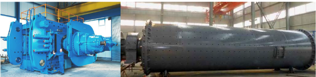
Grinding Technology
After the materials to be grinded have entered the grinding house shall be installed two (2) separate grinding lines to grant a total capacity of 6,000 TPD cement powder. So, each grinding line will be busy of about 14 hours daily. Furthermore, allows the two-line system at least one line to power down for maintenance ore using for another type of cement as fast harden cement (flash cement) where no Gypsum will be added for example. Each grinding line contains one Roller Press in front of every Ball Mill working. This Roller Press is created to reduce the clinker and Gypsum particle size to 0.2 mm by rolling press force. The ball mill itself has an inside two-section design in what different sizes of ball rounds grind the cement finer while passing section by section. At the end of the Ball Mill an O-SEPA™ separator divides the lower particles in direction of the cement silo transporting elevator and too large particles will be sent back to the entrance of the Ball Mill device in order to repeat the passing through the mill again. IRD Swiss recommends installing two (2) ball mills in a size of 3.9 x 13 M each together with two (2) Roller Presses 6 x 4 M in front of, in order to have grinding reserves in the capacity of each department. Both of every device in the row needs to be driven by SIEMENS motor and FLENDER gearbox, frequency controlled in turning torque and speed. The grinding department will be fully under the controlling software system, supervised from the central control cabinet by the leading responsible department process engineers
Cement Storage Technology To store the outcoming cement from the grinding department are Cement silos required. Regarding the ALHEDAB project has to be calculated a ten-day stock supply, that means to store 60,000 tons cement for each line. Therefore, will be 4 cement silos needed, every of 18M in diameter by 45M height. Those four cement silos have to be coupled to a cement tower bundle, in order to link them to each other for being flexible in usage.
In the grinding department will be collected from the two grinding lines the entire finished cement by one (1) short belt conveyor that moves the cement to an enlarged bucket elevator. This elevator lifts the whole cement amount up to the distributer on top of the silo tower bundle. Here the cement will be divided into the four cement silos on demand. Similar to the clinker silo is the height of the silo tower bundle limited to 48M by statics. IRD Swiss silo design does not need higher silos, we prefer 45-48M to store 10,000 tons in one (1) silo, so storing for one week of cement supply is being firmed. The single silos are connected to each other on top by the distribution system superstructure and on the bottom level by scraper tunnels and inspection hallways. Similar to the clinker silo a personnel lift elevator is installed here as well, where the tower bundle can be inspected and the distribution system can be maintained. The silos have to be performed in the same way as the other silos are made, particularly of concrete with smooth surfaced inner and outer walls. Central between the silos, located on the inner longitudinal axis is the output belt installed. This belt collects all the scraped out coming cement of each silo to move that to the next station, the packing and loading department where outer walls a similar large bucket elevator is installed to lift-up the cement on the top distribution system of the loading department house, in order to divide from the top of the building roof downwards to the particular packing stations
Cement Packing Technology To pack and load 12,000 tons of cement daily means to have a smart technology therefore. Unfortunately, we have found out that this stage of operating a cement plant is totally undeveloped in the Libyan cement industry. In all (!) cement plants we have seen on the way from Tunis to Libya, 3 plants in total, will be the cement, packed into 50 KG paper bags, loaded on flat-bed trucks piled up by hand loading staff, incredible.
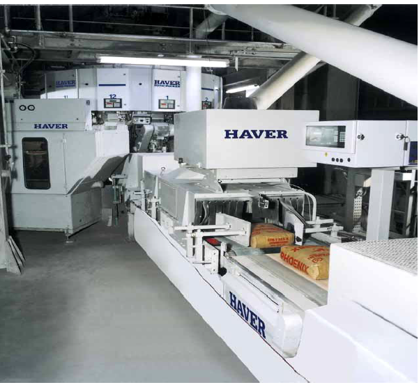
International up to date will be the cement packed into bags by rotary packers. Those automatic working filling stations can be installed from 6-16 spout-circular packers. But although those packers fill the cement automatic with the adjusted amount of cement the bags (paper and PP) have to be putted in by hand and the filled cement bags have to be taken out by hand. The new HAVER-ROTO-PACKER® packing station will be operated fully automatically. Therefore, will be the empty bags, coming delivered on a role, taken by a robot arm into the rotary packer spout by spout, will be filled and weighed, and finally be taken out and laid on discharging belt. The filled-bag discharge line represents the end of the packing machine and the transition between palletizing and loading. An adjustable discharge belt, which can be used for all standard bag sizes, transports the filled bags away from the packing machine. Next the bags are aligned on the bag aligning belt. Here the bags are cleaned on all sides by blowing air. As result, the packing department gets filled bags that are perfectly prepared for further transport and handling. The air is siphoned away continuously in order to keep the discharge line from getting overly dusty. At the check-weigher will be defined the maximum deviation of the filled bag weight. Should a bag not meet the specification, a diverter flap or another conveyor discards it. Next a cutting drum destroys the non-conforming bag and the product is caught and separated from the bag remnants and then reintroduced into the product process
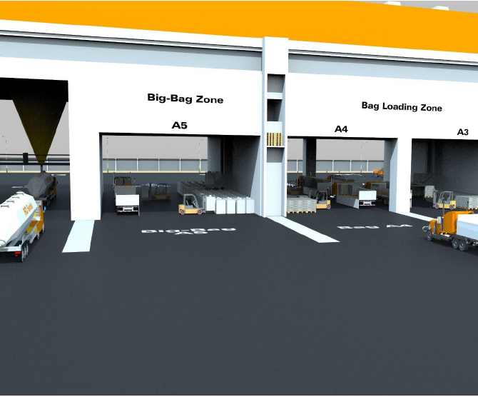
Cement Loading technology Loading the filled cement bags on the trucks picking-up by the cement customers of ALHEDAB should complete change to the loading technology of today. But therefore, ALHEDAB has to introduce a palletizing system similar to the European Pallet system that has been running for decades in Europe and United States. It guarantees ALHEDAB to operate the loading department cleaner and without overly dusty load within this department
In the loading department house are upstairs the rotary packers installed, that gets the loose cement via the divider funnels from the top of this building. We recommend installing 4 ROTO-PACKERS® for each cement line of 6000 TPD. Each packer is able to fill 2000 bags per hour, so in 20 h can be filled 2000 tons/packer, 8000 tons/day/per 6000 TPD line. So it keeps this packing department free of capacity stress. The discharging line that belongs to each packer piles the bags on a pallet and shrinks it simultaneously. Wall mounted pallet elevators move 4 pallets at once downstairs on the loading ground floor, where the trucks will be loaded with all the pallets by forklifts. It is obviously that this loading system safes loading time, independent of the fact that only a view bags will be damaged in a month. Counting the time being needed to load a flat bed truck with about 2000 bags by hand, it is surely not done in less than 2 hours and needs 10 loading staff people. We count for loading one truck with the same amount of 2000 bags (67 pallets) 15 minutes only, from palletizing to up-load the truck. Of course, every client has to run back the used pallets when picking-up the next cement order. If not doing so, he will lose his pallet ticket secure fee of maybe 10 LYD. This lending fee is up to ALHEDAB’s calculation for purchasing cost of new pallets generally, of course.
Cement Plant Process Control Technology Every line of the double line cement plant 2*6,000 TPD needs to be operated by a process controlling cabinet. This cabinet is located together with a quality management system, a task force operating group and a maintenance team in a separate building alongside by the kiln itself. On the top of those buildings is situated the process control tower, where all needed signal input from all plant departments will be reached by central process control computer server that is installed for each line. Seeing below this working station gives a small insight into the complexity of operating a cement plant with all belonging equipment to gain finally the most of the installed capacity of cement to be designed for the plant.
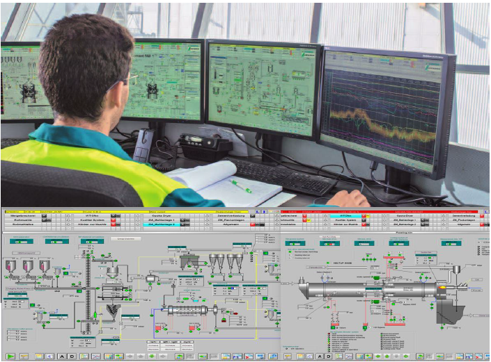
Since we introduced for IRD Swiss cement plant engineering we have started a strong collaboration with SIEMENS. Because of out- sourcing this branch the company DR. ECKLEBE Germany became our SIEMENS franchise partner for the CEMAT™ control and automation software system. To be fit in using this controlling process software every customer’s engineer staff will be trained in Germany for 6 weeks. Thereafter while running-up the plant, those group of engineers will be trained for second time in handling the own cement process departments by screens. Simultaneously will be trained the laboratory engineers additionally in dealing with the quality management and the cement lab equipment. This is a very important part of the plant to ensure the customers of ALHEDAB Cement quality standards for the cement to be sold. In many cases the clients want to get an issued cement quality report to be safe against construction and building company complaints as well as in case of any damages or other building control requirements of the customers. The mentioned task force group has to care about the kiln process in order to avoid kiln interruptions, by all mean, as that will be a lost.
Auxiliary Technologies
A lot of additional devices and auxiliary stations are being needed to run a cement plant, as there are filter systems to separate the cement dust from
the environment coming out via hot exhaust gases from the kilns and from the mill and grinding devices. Those filters except from the EP filter of the
pre-heater tower are construed as bag sampling system generally in order to run back the separated particles into the plant processes.
A water treatment plant has to be installed to safe water consumption as this is a big issue in the desert area of Nalut for the plant. We collect the most
of the sewage and re-circulate it in order to refresh as much as possible for feeding this water back into the cooling water circulation again. We have been known that ALHEDAB gets from Government the right of water withdrawal by one pipe from National water pipe network. So, we suggest
installing a very effective water treatment plant to avoid higher water consumption in general. Furthermore, will be an air compressor station required to provide the entire plant facilities with compressed air. Therefore, shall be established a central compressor device equipped with a distribution system to provide by pressure pipes the compressed air everywhere in the plant where needed.
For maintaining the cement plant have to be built at least 3 additional buildings, executed as lightweight constructions to provide the entire plant with a mechanical workshop, a storage facility for refractory brigs (lots of them will be needed during 1 year to repair the inner kiln walls as well as of the pre-calciners and a small building in same kind for spare part shops of every line.
To operate the traffic inside of a cement plant is a smart traffic plan required otherwise customer and supplier come in turbulences while moving in and out of the plant. IRD Swiss has been not only introduced a smart traffic plan, but has been created an own solution for the plant traffic in the entire plant area that allows to control the traffic very easily and secures the plant from cement thefts as well. That is why we strongly recommend to follow this very easy procedure and to install this special Sale & Load system. It needs to introduce a special SAP software for sales and ordering system - SAP-All®. Therefore, will be trained the key accountant staff as well as the security main officers in Germany for 4 weeks very detailed to guarantee a safe and fast sales and ordering system.
A modern cement plant needs to have a fenced area at all but moreover to clarify trespassing procedures. So, this study has to convince to set-up 2
gates only for passing the plant. There shall be one gate for in- and outgoing traffic of plant customers and a second service gate for passing the
supplier traffic to provide the plant with Clay, Sand, Gypsum and Iron ore. This service gate can be passed by the social area staff as well as the
operating labour force of the entire plant. Both secured and kept closed guard rooms will be operated by special security staff that needs to be chosen
by professional security company and has to be absolutely intransigent and must be staunch (loyal).
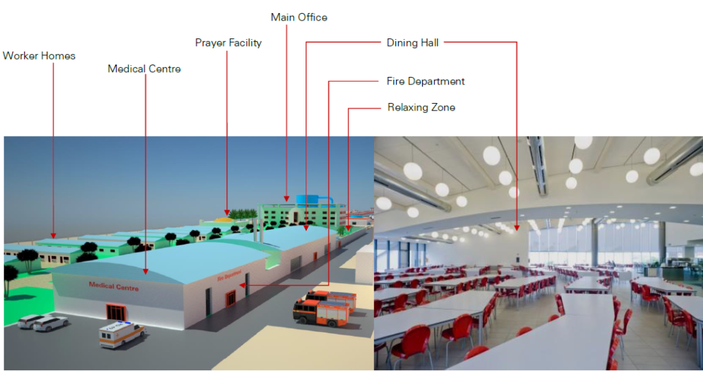
The study recommends from our experiences also to institute a fire department with at least two fully equipped firefighting cars and to institute an
emergency facility for fatal human accidents to be happen in every plant yet. Both facilities are well situated in the social area what this study consider
in an extra topic point that follows. ALHEDAB cement will be good advised to profit from our long-term experiences is such smaller details.
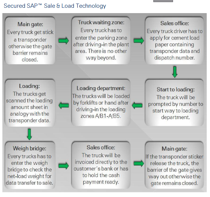
A sophisticated sales and loading software system is a very good possibility to save time, human resources and loss of money by customer frauds and thefts. SAP™ has therefore developed the SAP-All® sales and loading technology software system that not only collects data from loading department and sale office, but moreover the sale and the loading departments will be coupled in a logical way to speed-up the sales and loading procedures enormously. Simultaneously will be the plant secured against cement thefts what happens mostly during night shifts if non-loyal staff and bad customers try to trick the plant security in order to gain uncharged cement out of the plant. Such frauds happen more than the plant owners thinking. That is why the sale and loading procedure must be secured in the best way as the plant management can do. SAP secures sale & load technology, makes that real because it is easy to understand and does not need any special security hardware in addition to the normal plant security facilities. There are only a view things needed like the flexible transponder stickers of the long-life pagers for the drivers that needs to be purchased from time to time when running out. All interconnections to Banks are very safe nowadays, so no worry about sold cement charging. A stuff training will be organised to introduce this system.
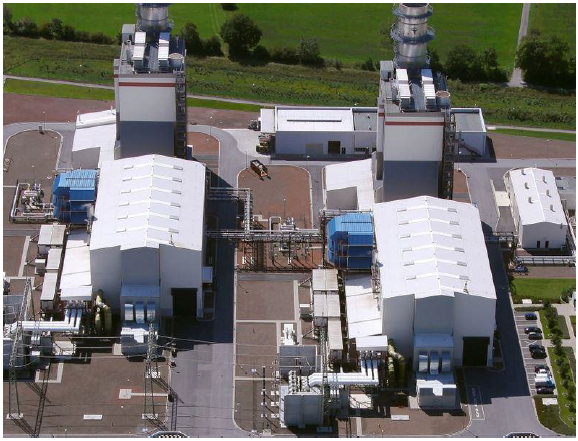
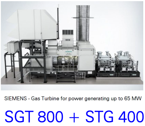
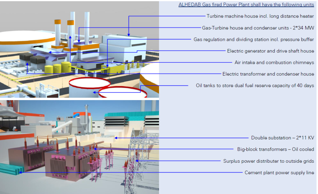
Power Plant – GAS fuel fired Because of the difficult situation in Libya concerning power supply of all industry companies we have been attracted on the fact that ALHEDAB Cement needs to install an own power plant, fired by the same fuels as for the kilns needed. Hence, we have to calculate for the double line plant 2*6,000 TPD → 65 MW power supply performance for each line. Both lines shall be provided separately from a double generator system of the power plant. IRD Swiss suggests installing two GAS turbines of 2*34MW, similar as shown below, driving two (2) SIEMENS generators by separate drive shafts. This method has the advantage to run the plant double layered and baked. So that the power station house has connected substation by using two (2) separate transformers that guarantees the plant a stable and controllable power supply with all needed high and low voltages. The gaining surplus power can be sold outer the plant if there are other consumers in the near field or maybe to inject into the National network grid. IRD Swiss announces that such a power plant needs up to 24 months from planning to run-up, so it has to start simultaneously with the erection of the cement plant itself. It is to intent to provide social area facilities with distance heat and to warm the main office building, labour accommodations in winter time and to supply the canteen kitchen with hot damp.
Social Area Keeping and hosting the labour staff and the engineers inside the plant as well as to set-up a main office, will be a social area needed, that shall be situated within a quieter corner area of the plant. The social tract has to be dimensioned for about 1,000 people to be accommodated and about 50 people in main office, they are not permanent living within the plant during the week. The following facilities shall be applied: